Balancing your engine...
When rebuilding an engine, you should consider it mandatory to have the
rotating assembly balanced. When the engine is spinning at 7000+ RPM, the
stresses involved on the cylinder walls, rod bolts, etc are incredible. Making sure that everything is balanced will ensure a smooth running and reliable engine.
What is the rotating assembly? The rotating assembly generally consists of:
The crankshaft
Pistons
Rods
Wrist Pins
Flywheel
Pressure Plate
Harmonic Balancer aka crankshaft pulley
The balancing process involves making sure that all of the pistons and rods
are the same weight. The lightest piston and lightest rod are used as the
"baseline" components. Then the remaining pistons and rods will have material
machined off of them until their weights match those of the "baseline" components. A weight that is equal to 1 piston + 1 rod + 1 wristpin is then clamped to
each crank throw to simulate the weight of the piston and rod. The harmonic balancer and flywheel/pressure plate combo are then bolted to the weighted crank. The whole assembly is spun in a fancy balancing machine that tells the machinist where material needs to be added/removed to achieve a balance. Most of the time, material is taken from the counterweights of the crank and/or the flywheel.
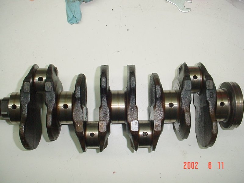
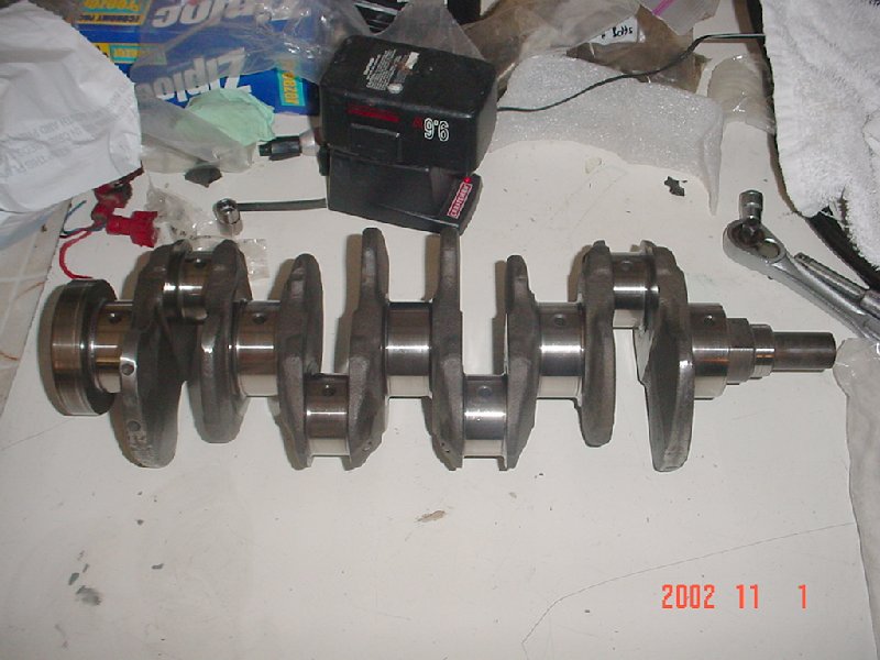
Here is a picture of the crank, fresh out of the engine:
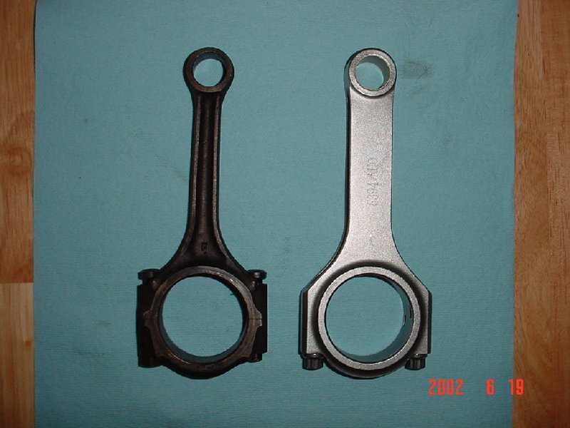
This is the stock 1987 D16A1 rod vs the new Eagle rod. The D series rods are definitely the weakest link in the engine. The 86-87 D series rod is the beefiest of all D series rods, but it is still not strong enough to stand up to a highly boosted engine. The Eagle rod is rated to withstand 600hp of abuse!
The Endyn/Wiseco pistons are beautifully machined pieces that are a tried-and-true choice. Matching them to the Eagle rods yields a piston/rod combo that is many times stronger than stock:
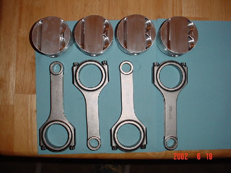
Here's a quick glance at the pistons and rods on their way to the balancing shop:
Here is a look at the now balanced and micropolished crank:
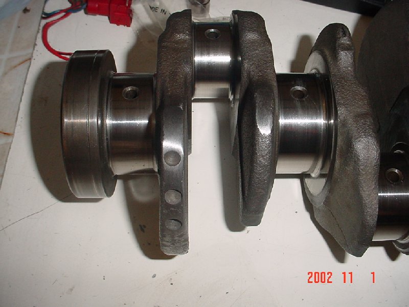
An up-close shot of the counterweights for the #4 cylinder. You can see where material was removed here:
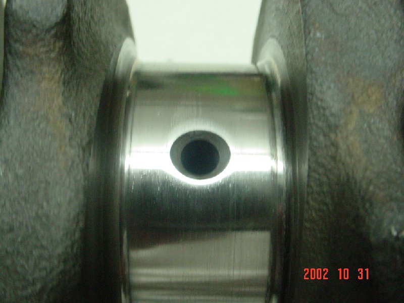
An up-close shot of the micropolished main bearing journal. This process was done using a special belt to remove impurities from the bearing surface:
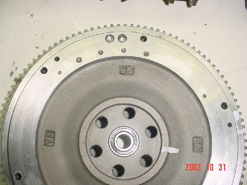
Lastly, you can see the holes that were drilled at the 12 o'clock position in my lightened flywheel (from a 91 CRX Si):
Back to main page