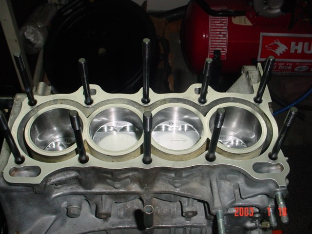
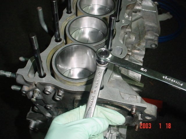
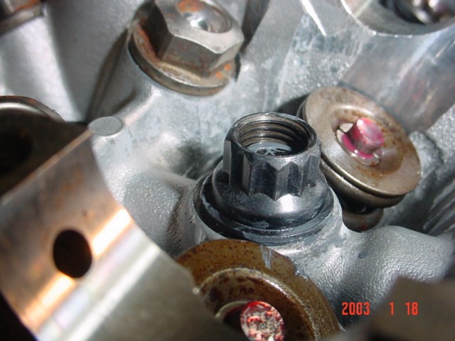
The double-nut method allows the stud to be torqued to spec. Another advantage of putting a little torque on the studs is that it allows every stud to sit at the same height. Finger-tight usually results in some studs being higher than others because the stud will often not reach the bottom of the threads before it feels tight.
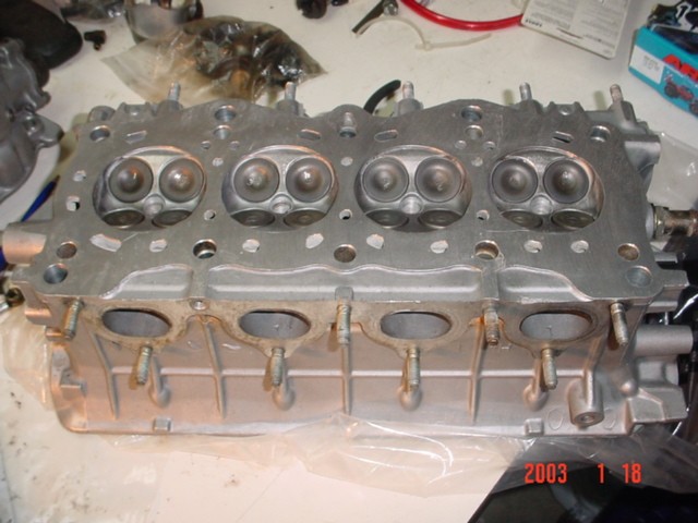
Here's a look at the cylinder head. A .004" clean-up cut was taken off of the bottom to ensure a perfectly flat surface. The head was completely disassembled and hot-tanked before resurfacing.
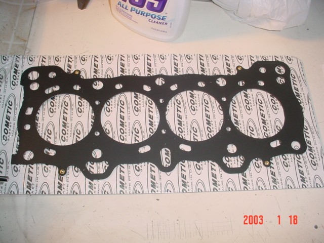
This is the bitchin' Cometic 3-layer steel gasket. It is .040" thick vs the stock .048". Since I decked the block, milled the head, and will be using a thinner headgasket, the camshaft timing will be altered. I will be correcting for this via cam gears. That's in the next chapter. :-)
These are the dowel pins that locate the head onto the block. This is an often overlooked area that can cause a lot of headaches. Since the head now sits closer to the block (about .030" closer due to decking/milling), I also shortened the dowels by the same amount. In some cases, failure to due this will result in a headgasket leak since the dowels will not allow the head to fully touch the block.

The headgasket got a coat of copper-coat spray to improve sealing and heat transfer. This is a common practice among many top engine builders and was something that I learned from my dad.
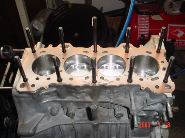
This head stud kit is actually not for this engine. The kit is for a VW engine, but it just happens to fit the D16A1/ZC engine. The only problem is the studs are just a little too short. Because of this, the washers included in the kit cannot be used. Using them would result in about 1/3 of the nut's threads not biting.
It's finally starting to look like an engine!

Here's another shot of the head installed. Honda used a ball-and-socket type rocker arm in this head.

The oil pressure "idiot light" sender is on the intake side of the block. Since I need a source of oil for the turbocharger, I will not be installing the sender in its original location. Instead, I will run a steel braided line from that location to a "T". The sender's thread hole is 1/8" BSPT. While the block was being worked on, I had the hole retapped to 1/8" NPT since NPT is far more common than BSPT. The steel braided lines that I am using use AN type fittings. So, I needed a 1/8" NPT to -4 AN aluminum adapter.

Here we are after all of the little stuff was put back on the intake side of the block. These items included the water pipe (connects the water pump to the thermostat), the crankcase oil separator, the oil cooler, 1/8" NPT to -4 AN adapter, and the nipple that supplies water to the oil cooler.
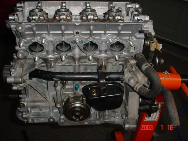
I installed a brand new water pump and called it a day.
